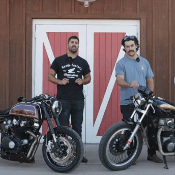
A couple of weeks ago I spent a few days with Matt at his Krank Engineering workshop. Matt had agreed to help me fit a set of “universal” Tarozzi rearset footpegs. This was a stage of my cafe racer build that I’ve been meaning to do for years so it was a rather momentous occasion. Of course, like any custom project, the task wasn’t without its challenges. The install threw plenty of issues at us, but with Matt’s extensive knowledge and my naive enthusiasm, we got the job done.
Matt, being the diligent customiser that he is, documented the process which you can read below. First, I thought it may be pertinent to explain why you would want to install rearset footpegs on a cafe racer. Rearset footpegs are essentially a racing component. Most sportbikes these days run footpegs that can be categorised as rearsets and any motorcycle you see at classic racing events will be running them. Their basic function is to move your feet further back and higher. The result is increased ground clearance so that at full lean your feet and pegs stay clear of the asphalt.
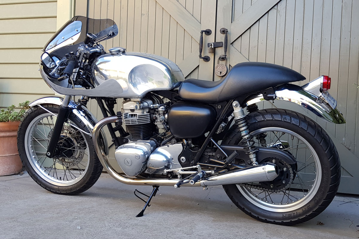
I openly admit it’s rare that I would ever tip my W far enough over to scrape the footpegs. So why install them? One of the first things I did during my cafe racer build was to install clip-on handlebars. Clip-on handlebars result in a forward-leaning riding position. With the stock, mid-mounted footpegs your thighs sit parallel to the ground. When you lean over further you are putting additional strain on your muscles and restricting blood flow. Over time this can lead to discomfort, especially on longer rides. Oh, and let’s not forget they look great.
With all that in mind here’s Matt with the step by step process of how to install rearset footpegs on a cafe racer.
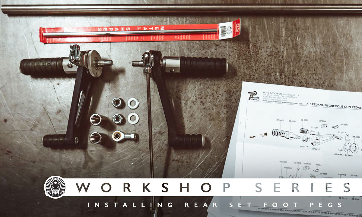
Matt: I generally take the approach that anything is possible…with time and money. This job was no different. With the set of universal Tarozzi rearsets that Geoff (aka Return of the Cafe Racers) had, I promised him we’d “make them fit” his Kawasaki W650.
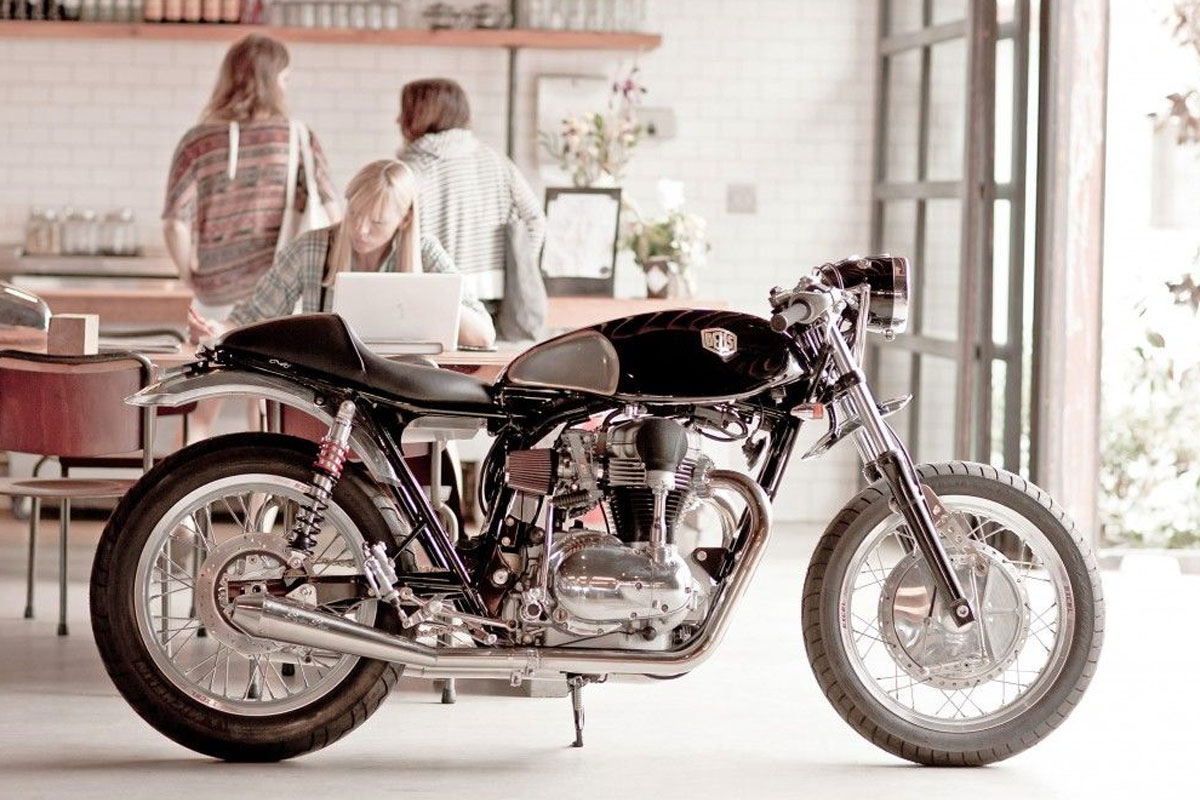
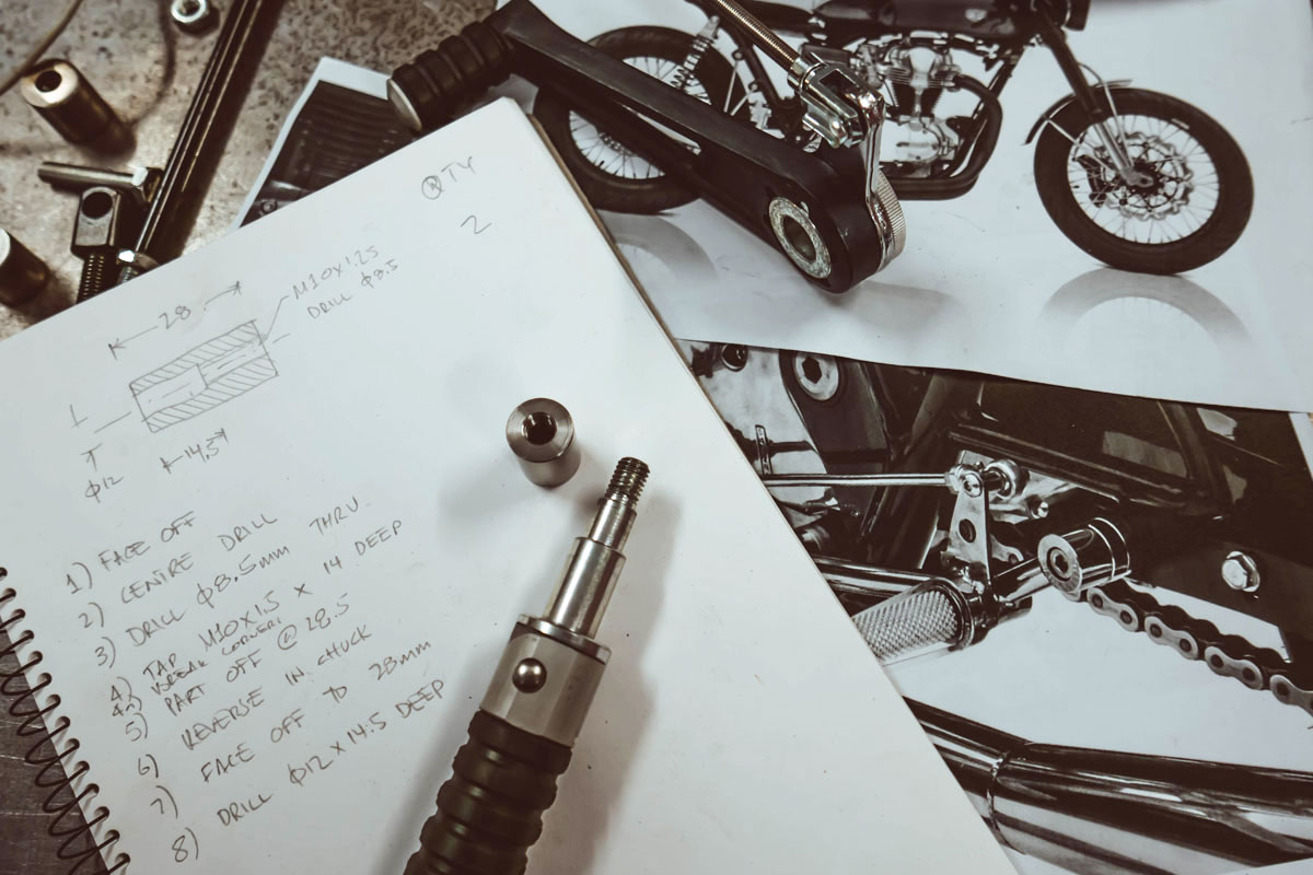
Geoff had a photo of a pair of different rearsets fitted to the Deus Fiddler W650 build (above), and we essentially mimicked their mounting method. Their approach was to use both the stock footpeg mount and the stock exhaust bracket on the rear of the frame. These two points anchored the “bridge” that allowed the rearsets to be mounted between. Obviously, not all bikes will offer this solution, but with Geoff’s W650 we got lucky.
Step 1: Planning and materials
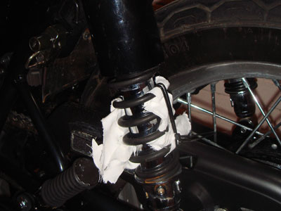
First, we removed the stock footpegs. The footpegs mounting bolt also holds a bracket on Geoff’s aftermarket exhaust and is secured to a threaded steel block on the frame. This bolt was special, a fine thread metric 12mm bolt (M12 x 1.0mm).
There isn’t a lot of space around the footpeg mount, so, similar to Fiddler, we elected to fabricate stainless steel bungs that we could use to support our bridge. However, the stock footpeg mount is quite thick; maybe 10mm. Without the thickness of the footpeg mount in place, the exhaust would be pulled inwards to the frame, which we wanted to avoid.
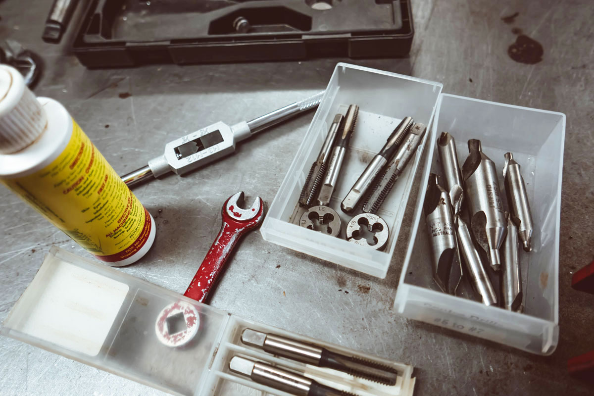
I found a scrap of stainless steel flat bar stock, and we figured we could make a spacer to fill the gap that the footpeg used to occupy. Geoff’s bike has an aftermarket exhaust, which conveniently freed up the rear bracket mount. The rear bracket already had threaded weld nuts which also made things easier. After a quick measure, I found they were tapped to suit a metric bolt (M8 x 1.25mm). This was an easy one, we’d just make a bung that could be screwed to the existing M8 threaded hole. To make it look slick, we’d “counterbore” the bung so a socket hex bolt could recess within the bung.
ED: Not sure how to identify bolts? Check out this article on the Krank Engineering site.
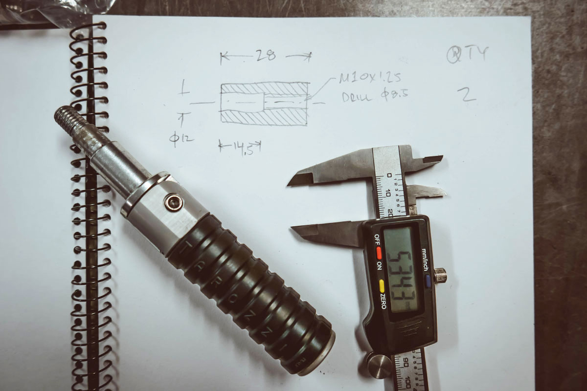
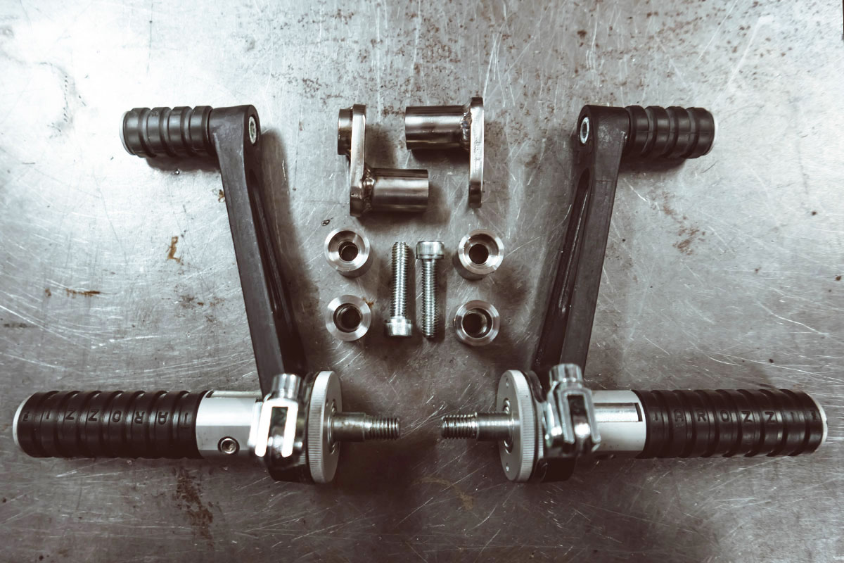
The Tarozzi rearset footpegs are designed to screw into some sort of fitting with a metric 10mm thread (M10 x 1.5mm). We took some measurements, and I designed and sketched up the special bung we’d need to install them. This bung would sit somewhere around the middle of the bridge.
Step 2: Fabricating rearset mounting points
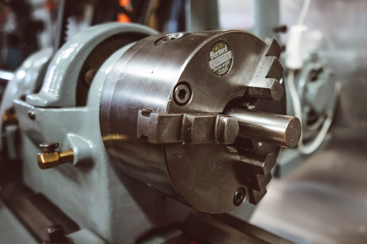
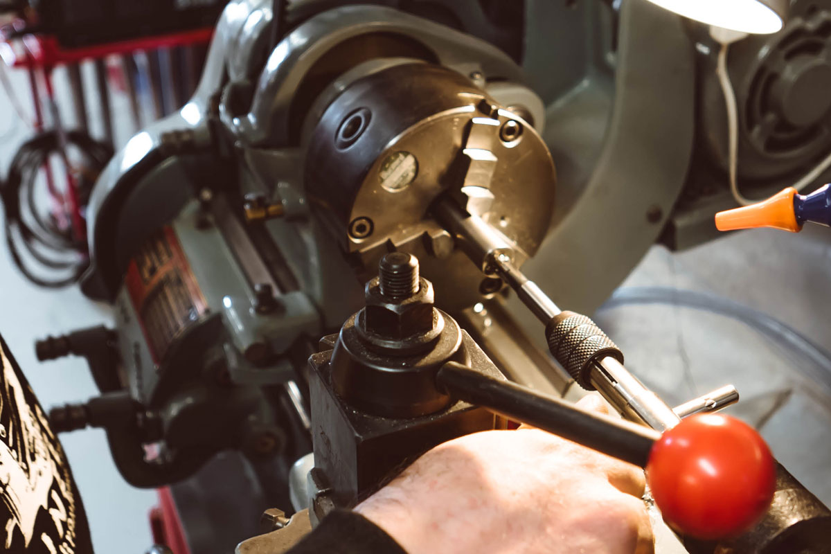
The front bungs were the easiest so we smashed those out first. Geoff had some 19mm diameter stainless steel bar stock for the project, so we chucked it up in the lathe, faced, chamfered and parted (cut) it off to 40mm long.
The middle/footpeg bungs were next. There were quite a few machining operations to get them done, so I took a few minutes to write them out. That way, I wouldn’t forget a step halfway through. We faced off the bar to square the end and drilled an 8.5mm clearance hole all the way through. This left us with a hole a the correct size for tapping the M10 x 1.5mm thread. It’s easier to keep the tap straight if you use the lathe, so we started tapping out the 10mm thread in the lathe.
Then we parted the bung off the bar stock, flipped it around and put it back in the lathe. Next we faced off the other end and drilled part way into the bung with a 12mm drill. This created a hole that would accommodate the unthreaded section of the Tarozzi footpeg.
The bungs for the rear exhaust mount were straightforward. Chuck up the bar stock, face off the end and drill an 8mm hole straight through. The special step was counterboring. A counterbore is a tool that acts like a drill but creates a flat-bottomed hole. We drilled the counterbore then parted the bung off. Again we flipped the piece in the chuck and face off the other end to clean it up. Voila, we a full set of bungs!
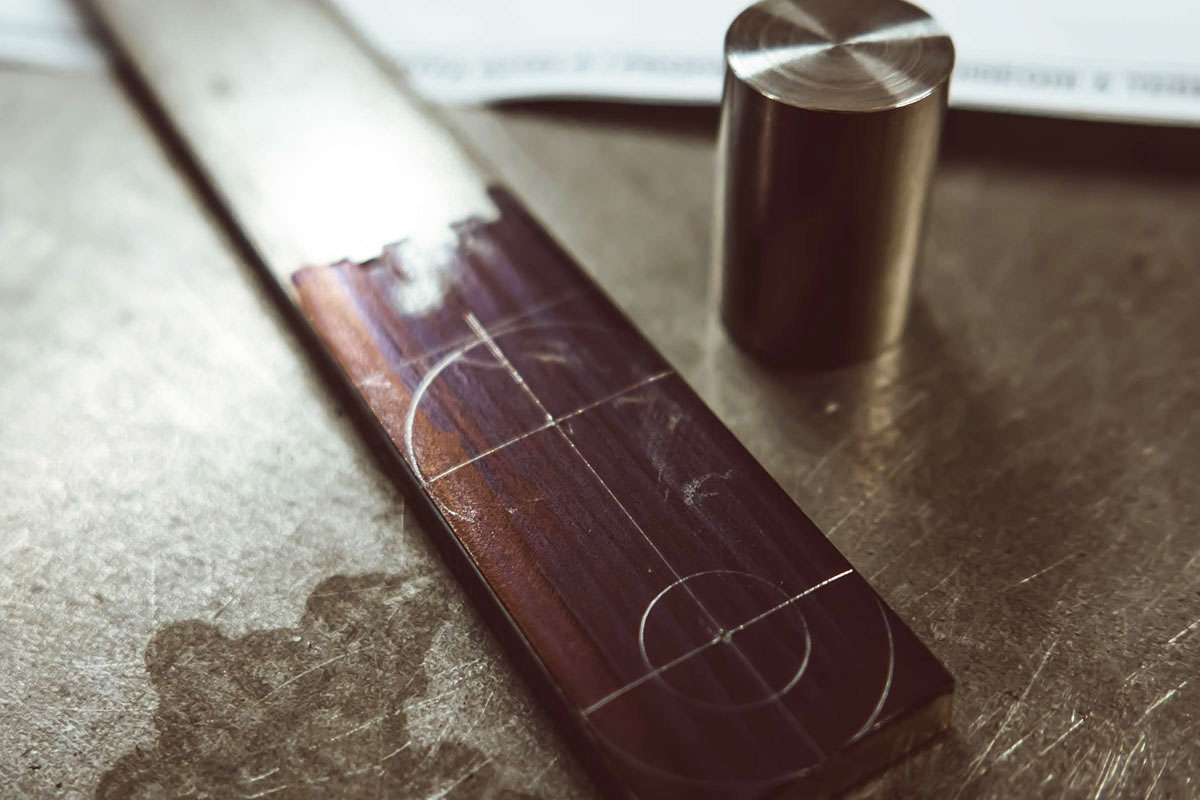
I then marked out a simple shape on the stainless steel flat bar to make our spacer. It’s easier to hold the whole piece of stock in a vice while drilling the holes. You could cut it out first, but I prefer to drill all the holes while its part of a larger piece of metal. Then we cut out the spacer piece with an angle grinder and sanded and filed the edges smooth.
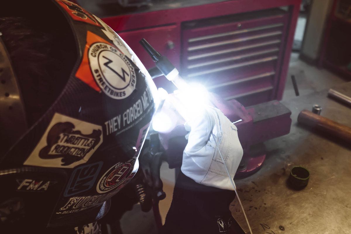
The front bungs could now be welded to the spacer plates. Since these parts are all stainless, we used my preferred welding method, “Gas Tungsten Arc Welding” (GTAW), more commonly known as “TIG”, which stands for “Tungsten Inert Gas”.
ED: Watch Matt’s Krank Engineering introduction to welding video here.
Part 3: Measuring and aligning
Once the first bungs were welded to the spacers, we installed them on the bike in their final location. With the other bung installed on the rear exhaust bracket, we now had two fixed points to build our bridge on.
At this point, we decided the exact location of the third footpeg bung. With the pegs screwed into the custom bungs, we had to position them to clear the exhaust and locate an appropriately sporty position for them to sit. We spent ten minutes looking at it and holding the footpegs in a few different locations before we settled on a location.
While holding the footpeg in the desired position I took a measurement to the rear bung. This gave us the length of the first half of our bridge. During this stage, we had to be mindful of the orientation of the footpeg bung. When the footpeg is screwed tight into the bung, we wanted it positioned so the peg folds upwards on its bracket as designed. If the bung was welded into the bracket “misaligned”, the footpeg wouldn’t fold directly upwards. The rear bung doesn’t care which orientation it’s in, so I chose to weld this one first.
Geoff had brought some solid 16mm stainless steel bar stock for the “bridge” pieces. We chopped one off at 50mm then put a large chamfer on it. I wouldn’t (and couldn’t) have done this on tube, but I wanted a very strong weld between the bungs and the bridge pieces. When you’re changing direction when riding, you push off the footpegs to move your bodyweight. It was essential that we had a strong connection.
4. Welding the rearset bracket together
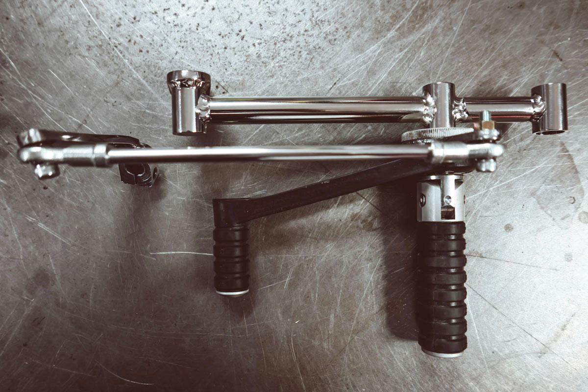
As I mentioned, it didn’t matter where the bridge piece was mounted around the rear bungs perimeter. So, we clamped it up and lightly tack welded it to the spacer. We then remounted the part, positioned the footpeg bung and marked where it needed to sit. We then removed them again, clamped them down and tack welded them together. Now we need to determine the length and location of the other bridge piece.
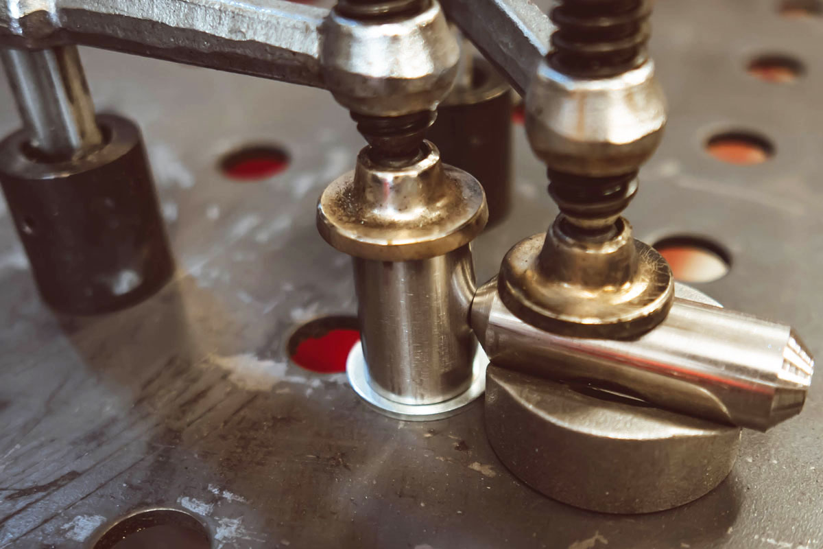
Reinstalling all our parts (again!), we could measure the length of the front bridge piece. We then cut and chamfered a piece similar to the others. For this piece, I wanted to tack weld it in-situ (on the bike), mainly to ensure everything would fit properly once it was fully welded and returned to the bike. So we rigged up some woodworking clamps to hold the whole contraption together. I buzzed a couple of tacks between the bridge piece and the bungs and we had our part mocked up.
When welding, you can expect some movement of a joint due to the heating and cooling of the metal. I was expecting this could be enough to prevent the whole bracket from fitting back on the bike, so we had to be careful. In a production environment, you’d have a heavy steel jig to hold all the parts while welding to prevent them moving. Alas, when you are doing a “one-off” in your home workshop, you need to come up with an alternative. I clamped the bracket to my welding table but it is a complex shape so it wasn’t possible to completely secure using the equipment I had.
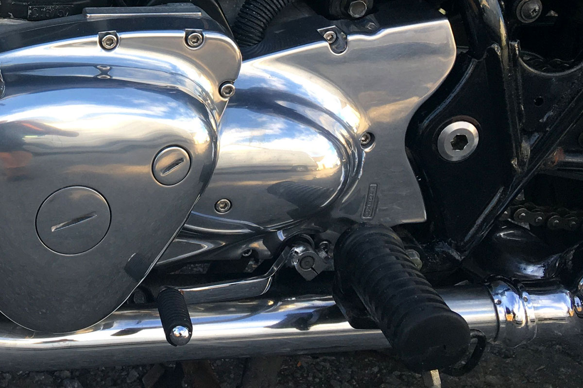
In this case, I ran a small weld at each joint, then doused the bracket with water to cool it. Then I dried it off, ran a bit more weld and doused it again. Rinse and repeat many times before all the joints were completed. Thankfully the bracket didn’t suffer from any distortion during welding and our almost complete bracket bolted straight back onto the bike. Mission accomplished!
While I was welding the bracket for the other side, Geoff got stuck into the buffing. By the time I was done he’d polished the stainless steel bracket to a mirror shine. This is easy to do with a bench grinder and some buffing equipment from your local hardware shop.
ED: Here’s another Krank Engineering article on how to restore and polish metal.
5. Installing rearset footpegs & problem-solving
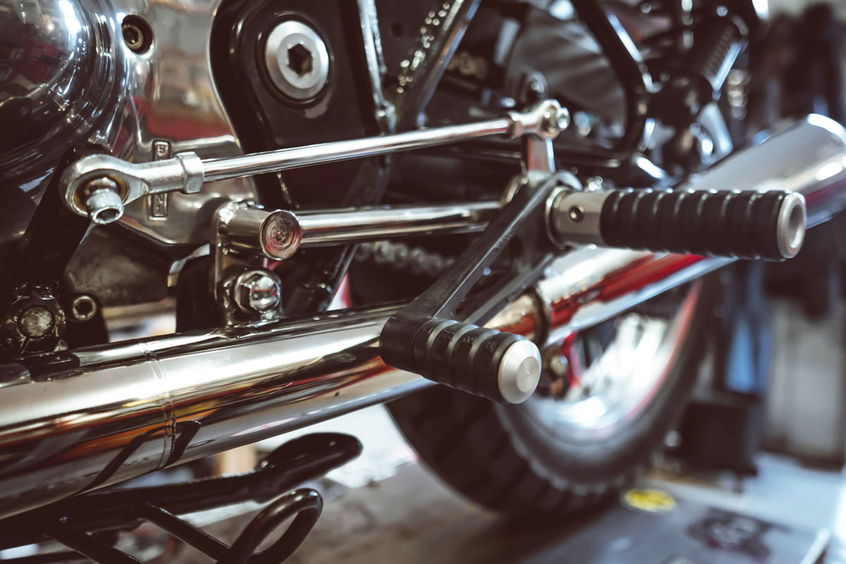
On the left side, we needed to connect the Tarozzi peg to the shift linkage. This was relatively simple with a couple of rose joints and some threaded rod. We also installed a thin aluminium tube over the threaded rod for a super clean finish. The stock shift pedal required a permanent modification. We cut it down and drilled a hole for the bolt to connect the shifter to the rose joint. We then rotated it around so it was close to parallel with the footpeg bracket.
The most painful part of the project was adjusting and reconnecting the rear brake linkage. It was a lot of trial and error to re-shape the existing linkage. We had to make several bends to snake the linkage up between the swing arm and exhaust. Believe it or not, getting the rear brake working properly ended up taking longer than making the rearset brackets!
Three days after starting, we finally had it looking right and functional. We still need to solve the rear brake light switch problem. With a custom job like this, it is simply an exercise in problem-solving, one after another!
Special thanks to Matt McLeod.